Cathode Ray Oscilloscope-Principle and Construction of Cathode Ray Oscilloscope
 written by Adeel abbas
Cathode Ray Oscilloscope is an instrument that is used in laboratories to measure voltage signals. The features of the Cathode Ray Oscilloscope like reliability, stability, and ease of operation make it suitable as a general-purpose laboratory instrument.
Cathode Ray Oscilloscope
A device that traces the desired waveform with a beam of electrons or cathode rays is called a cathode ray oscilloscope (CRO).
An electronic device is used for plotting graphs at a very high speed.
Basic Principle of Cathode Ray Oscilloscope
A beam of electrons is deflected while passing through a uniform electric field present between two sets of parallel plates.
This beam then falls on a fluorescent screen where it makes a visible spot. It can display graphs of functions varying rapidly with time.
Construction of Cathode Ray Oscilloscope
It consists of a highly evacuated glass tube. One end of the tube has an electron gun that produces a beam of electrons and the other end has a fluorescent screen that is counted with a material like Zinc sulfide.
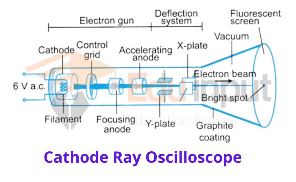
Electron gun:
It consists of an indirectly heated cathode, a grid, and three anodes and provide a beam of electrons. The filament F heats the cathode which emits electrons.
The anodes are at a high positive electric potential with respect to the cathode. They not only accelerate the electronic beam but also focus them on a fixed spot on the screen S
Grid:
The grid G is at a negative potential with respect to the cathode. It controls the number of electrons that are accelerated by anodes and so it controls the brightness of the spot formed on the screen.
Deflecting plates:
X and Y are the two sets of deflecting plates. When voltage is applied between the plates, it deflects the beam horizontally on the screen parallel to the x-axis.
When voltage is applied across the Y plates it deflects the beam vertically on the screen along the y-axis.
Sweep or Time Base Generator in CRO
The voltage that is applied across the x-plates is usually provided by a circuit that is built in the CRO it is known as Sweep or Time Base Generator.
Its output wave form is a saw tooth voltage of period T. The voltage increases with time for a period of T and then drops to zero.
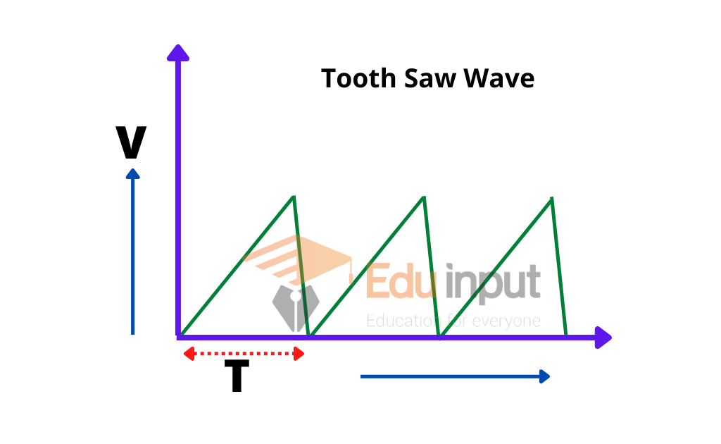
When this voltage is applied across the x plates then the spot is deflected linearly along the x-axis for a time T the spot then returns to its starting point on the screen very quickly because the saw tooth wave falls to its initial value at the end of each period.
If the time period T is very small we see just a bright line on the screen.
CRO Waveform
If a sinusoidal voltage is applied across the Y plates and a time base voltage is applied across the x-plate then the sinusoidal voltage will appear as a sinusoidal trace on the screen.
The pattern will appear stationary if T becomes equal to a time period or some multiple of the voltage on y-plates.
It is thus necessary to synchronize the frequency of the time base generator with the frequency of the voltage at the y-plates.
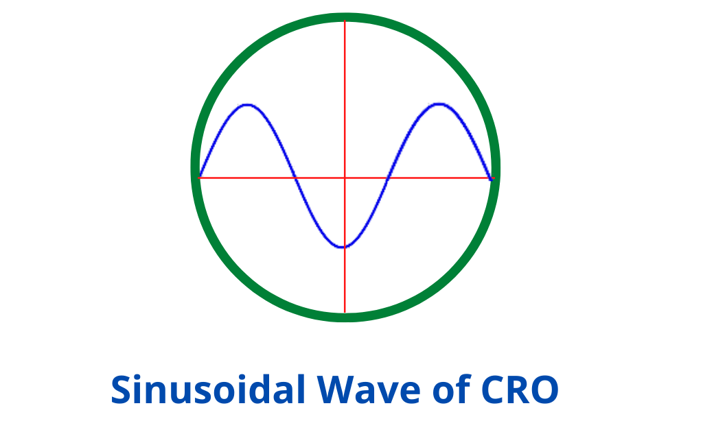
This is possible by adjusting the synchronization controls provided on the front panel of the CRO.
Uses of Cathode Ray Oscilloscope
1) The CRO is used for displaying the waveform of a given voltage.
2) When the waveform is displayed, we can measure the voltage, frequency, and phase.
3) As the y-axis is calibrated in volts and the x-axis in time, the instantaneous value and peak value of the voltage can be measured
4) The time period can also be determined by using the time calibration of the x-axis.
The phase difference between two voltages can be obtained by displaying their waveform. The waveforms of two voltages are shown.
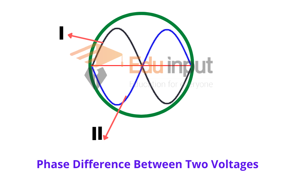
These waveforms show that when the voltage of I is increasing, the voltage of II is decreasing and vice versa. This phase difference between these voltages is 180.


Leave a Reply