Transformer-Types of Transformer and Working of Transformer
 written by Adeel abbas
The transformer is an electrical device that is used to transfer electrical energy from one alternating circuit to another circuit. The transformer is widely used in the electrical power industry.
Transformer
It is an alternating device that converts an alternating emf into a larger or smaller alternating emf.
Working Principle of Transformer
It works on the principle of mutual induction between two coils. The transformer is a simple electrical device that works on the principle of Faraday’s law of induction by converting the electric current into a larger or smaller value.
Construction of Transformer
A transformer consists of two coils of copper electrically insulated from each other, wound on the same iron core. The coil to which A.C. power is supplied is called Primary and that from which power is delivered to the circuit is called the Secondary.
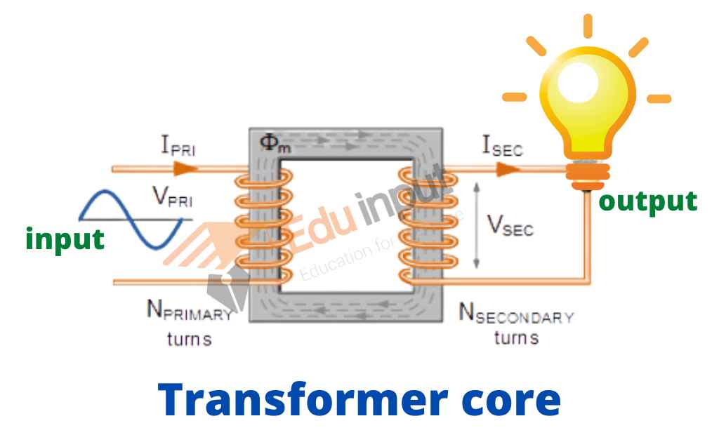
There is no electrical connection between the two coils but they are magnetically linked.
Working of Transformer
Suppose that an alternating current is applied to the primary. If at some instant t, the electric flux in the primary is changing at the rate of Δφ/Δt then there will be back emf induced in the primary which will oppose the applied voltage. Hence, the self-induction
Self induced emf = -Np (Δφ/Δt)
If the resistance of the coil is negligible, then the back emf is equal and opposite o the applied voltage Vp so
Vp = – (back emf)
Vp = – ( -Np (Δφ/Δt)
Vp = Np (Δφ/Δt)
As the flux through the primary also passes through the secondary, so the two coils are tightly coupled, and the rate of change of flux in the secondary will also be Δφ/Δt.
Thus,
Vs= Ns (Δφ/Δt)
Dividing the Vs and Vp
Vs / Vp = Ns / Np
This is the required transformer equation.
Types of Transformer
There are different types of transformers that are classified on these factors.
- Voltage Range
- Medium of Core
- Install Location
Classification based on voltage
They can be classified into two categories based on the voltage range.
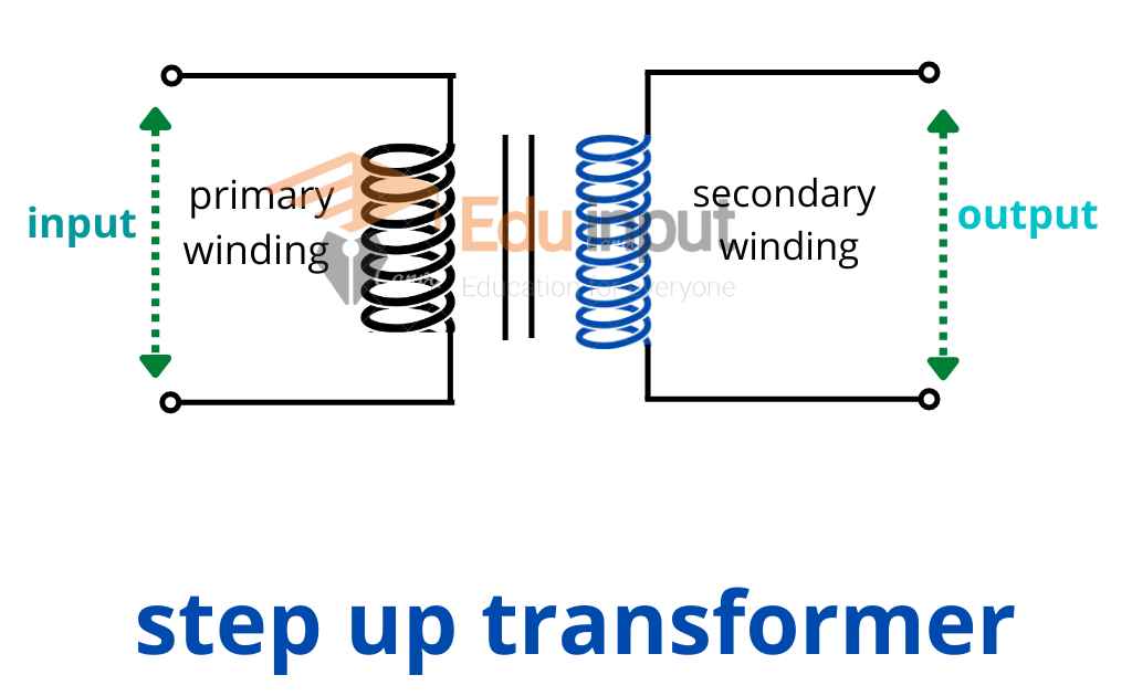
Step-Up transformer
If Ns > Np then Vs > Vp such a transformer in which the voltage across the secondary is greater than the primary voltage is called a Step-up transformer.
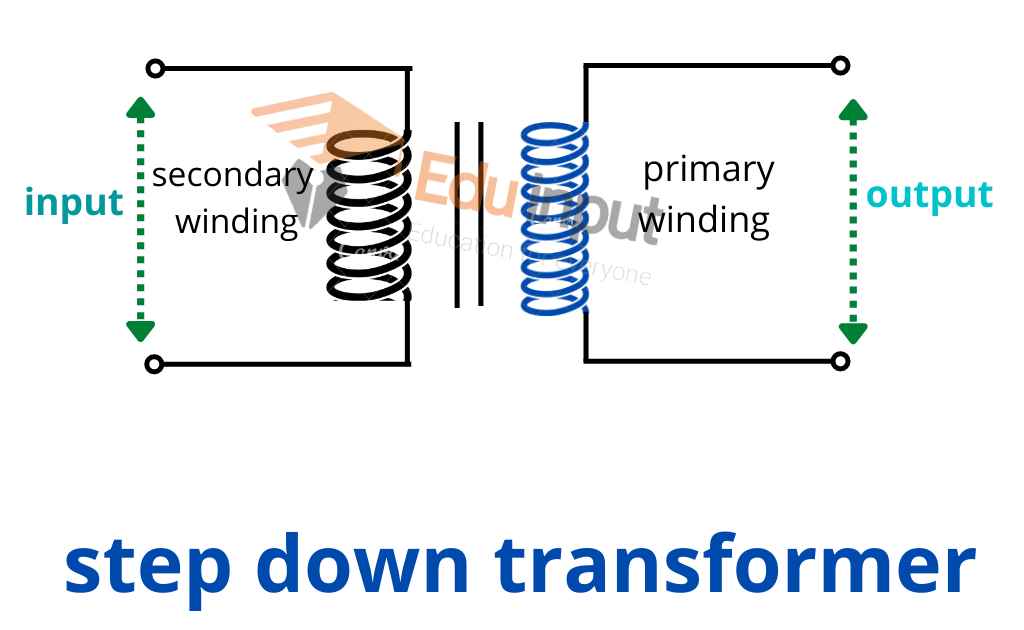
Step-Down Transformer
If Ns < Np then Vs < Vp such a transformer in which voltage across the primary is greater than the secondary voltage is called a Step-down transformer.
Classification based on Medium of Core
Transformers are divided into two parts on the basis of the medium of the core.
Air Core Transformer
The primary and secondary windings are linked by the flux that flows through the air. Windings are the coils or strips of wire wound onto the non-magnetic strip.
Iron core Transformer:
In an iron core transformer, a perfect linkage path is provided by the windings on multiple iron plates stacked together.
Classification Based on Install Location
The transformer is also classified on the basis of the location of its installation.
Power Transformer
A power transformer is a static machine that converts electrical power from one circuit to another without changing the frequency.
Distribution Transformer
Distribution Transformers are mainly used at domestic distribution points to collect goods coming in from various locations. These are designed for carrying low voltages, which makes them easy to install and characterized by low magnetic losses.
Power of Transformer
Electrical power in a transformer is transformed from its primary to the secondary coil by means of changing flux. For an ideal transformer
Power input = Power output
VpIp = VsIs
Vs /VP=Ip/Is
Thus the currents are inversely proportional to their respective voltages.
Uses of Transformer
Transformers are used in electric supply. When current ‘I’ passes through a resistance ‘R’ economically, then the power loss is due to the effect of current (heating effect).
To minimize the loss during transmission, it is not possible to reduce ‘R’ because it requires the use of thick copper wire which becomes highly uneconomical. Thus it is achieved by reducing “I”.
Increasing the voltage using a transformer reduces the current. Inside a house, a transformer may be used to step down the voltage from 250 volts to 9 volts for ringing a bell or operating a transistor radio.
Transformers with several secondaries are used in television and radio receivers where several different voltages are required.
Power loss in Transformers
For an ideal transformer, Input power is equal to Output power.
But in an actual transformer, Output power <Input power.
There are two main causes of power loss:
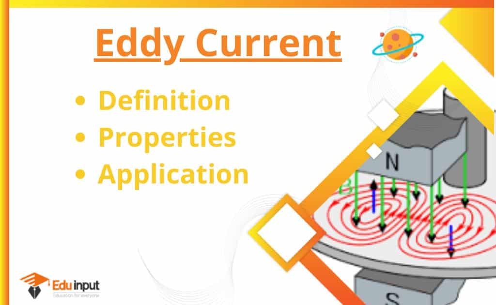
1) Eddy Currents:
As magnetic flux changes through a solid conductor, induced Currents are set up in closed paths in the body of the conductor.
These Induced currents set up in a direction perpendicular to the flux are known as Eddy currents.
It results in power dissipation and heating of the core material. It can be minimized if the core is laminated with insulation in between the layers of laminations which stops the flow of eddy currents.
2) Hysteresis:
The energy used to magnetize and demagnetize the core material in each cycle of the A.C is called Hysteresis loss.
The efficiency of a transformer:
The efficiency of a transformer is defined as;
E=Output power/Input power × 100
Factors increasing efficiency:
- The core should be assembled from the laminated sheets of a material whose hysteresis loop area is very small.
- The insulation between lamination sheets should be perfect so as to stop the flow of eddy currents.
- The resistance of the primary and secondary coils should be minimum.
- Since power transfer from primary to secondary takes place through flux linkages, the primary and secondary coils should be wound in such a way that flux coupling between them is maximum.

Leave a Reply