What is Voltmeter?- Symbol, Types, And Uses
What is Voltmeter?
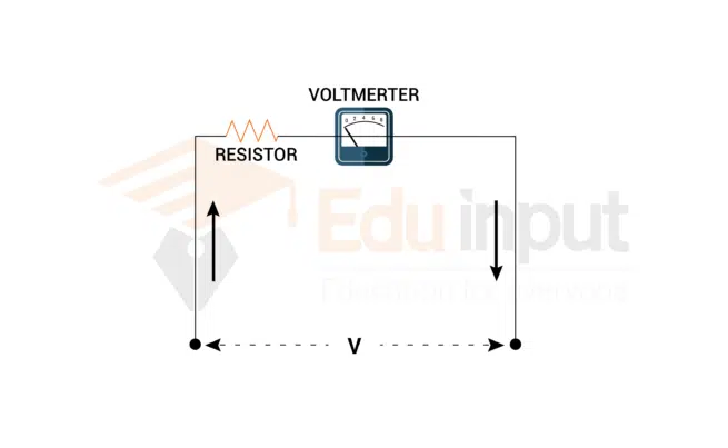
The voltmeter is an electrical instrument used to measure the voltage or potential difference between two points in an electrical circuit. They are commonly used in various applications across industries, laboratories, and households.
A voltmeter is an essential electrical instrument specifically designed to measure the voltage or potential difference within an electrical circuit. It is primarily calibrated in units of volts with millivolts (0.001 volts) or kilovolts (1,000 volts).

A voltmeter is connected in parallel to the device to determine the voltage of a device or component. This parallel configuration is very important because objects connected in parallel typically share the same potential difference.
One distinctive feature of a voltmeter is its high internal resistance. This characteristic is intentionally incorporated into the design to ensure accurate voltage measurement between two points in a circuit.
Due to high internal resistance, the voltmeter allows only a minimal amount of current to flow through it. Consequently, the flow of current is impeded and enables the voltmeter to provide precise and reliable voltage readings. This parallel connection ensures that the voltmeter accurately reflects the potential difference present within the circuit.
In electrical circuits, it is important to distinguish between different measuring instruments to accurately assess the characteristics of the system. There is a difference between a voltmeter and an ammeter. An ammeter is used to measure the electric current, while a voltmeter is used to measure voltage.
Voltmeter Symbol
The symbol for a voltmeter in electrical circuit diagrams consists of a circle with a “V” inside, representing the measurement of voltage across a specific component or between two points in a circuit. The voltmeter is usually connected in parallel to the circuit or component being measured.

Types of Voltmeter
Voltmeters can be categorized into two types:
Each type has its own advantages and applications.
Analog Voltmeters
Analog voltmeters utilize a moving coil mechanism and a pointer to indicate the voltage reading on a calibrated scale. They often employ electromagnetic principles for their operation. Within analog voltmeters, there are two subcategories:
Moving Coil Voltmeters (MCVs)
MCVs work on the principle of a current-carrying coil placed in a magnetic field. The current in the coil generates a torque that causes the coil to rotate. The angular rotation is proportional to the voltage being measured.
Moving Iron Voltmeters (MIVs)
MIVs use a moving iron element instead of a coil. The iron element moves due to the magnetic field produced by the current flowing through the circuit. The deflection of the iron element indicates the voltage reading.
Digital Voltmeters
Digital voltmeters provide a numeric display of the voltage reading, making them easier to read and more precise. They use analog-to-digital converters (ADCs) to convert the input voltage into a digital format. Digital voltmeters can be further classified into two types:
Ramp-type Digital Voltmeters (RDVMs)
RDVMs measure the time it takes for a capacitor to charge from zero to the input voltage. This time measurement is then converted into a digital display of the voltage reading.
Integrating Digital Voltmeters (IDVMs)
IDVMs integrate the input voltage over a specific time interval to determine the voltage reading. They provide high accuracy and are commonly used in laboratory settings.
Uses of Voltmeters
Voltmeters find widespread application in numerous fields due to their ability to measure voltage accurately. Some key uses of voltmeters are as follows:
- Circuit Testing and Troubleshooting: Voltmeters are essential tools for testing circuits and diagnosing electrical faults. They allow technicians to measure the voltage at various points in a circuit, ensuring correct functionality and identifying any issues.
- Power Quality Analysis: In electrical power systems, voltmeters help monitor and analyze power quality parameters such as voltage fluctuations, harmonics, and transients. This information assists in maintaining stable and efficient power distribution.
- Battery Testing: Voltmeters are commonly employed to measure the voltage of batteries, ensuring they are charged properly and providing an indication of their remaining capacity.
- Industrial Control Systems: Voltmeters play a crucial role in industrial control systems, where voltage monitoring is necessary for maintaining the safe and efficient operation of machinery, motors, and equipment.
Related FAQs
What is the basic concept of a voltmeter?
The basic concept of a voltmeter is to measure the voltage or potential difference between two points in an electrical circuit. It is designed to provide an accurate reading of the electrical potential at a specific location.
What is a voltmeter and what is an ammeter?
A voltmeter is an electrical instrument used to measure voltage, while an ammeter is used to measure electric current. While a voltmeter measures voltage, an ammeter measures the flow of electric current in a circuit. Both instruments are essential for understanding and analyzing electrical systems.
What is the symbol and use of the voltmeter?
he symbol for a voltmeter in circuit diagrams consists of a circle with the letter “V” inside. This symbol represents the measurement of voltage across a specific component or between two points in the circuit. The voltmeter symbol indicates where the voltmeter should be connected in the circuit to obtain the desired voltage measurement.


Leave a Reply