Rectification In Physics-Half Wave Rectification and Full Wave Rectification
 written by Adeel abbas
The process of converting the A.C waveform into the D.C waveform is called rectification. Rectification is the process of turning an alternating electric current waveform into a direct current waveform.
The device used for rectification is called a rectifier. Two PN junction Semiconductor diodes are extensively used for this purpose.
Methods of Rectification
There are very common methods of rectification.
- Half-wave rectification
- Full-wave rectification
Half Wave Rectification
A type of rectification in which only one-half cycle of the input AC current is converted into D.C. current is called Half-Wave rectification.
A diode is connected in series with a load resistor and they are connected to an alternating voltage source of period T.
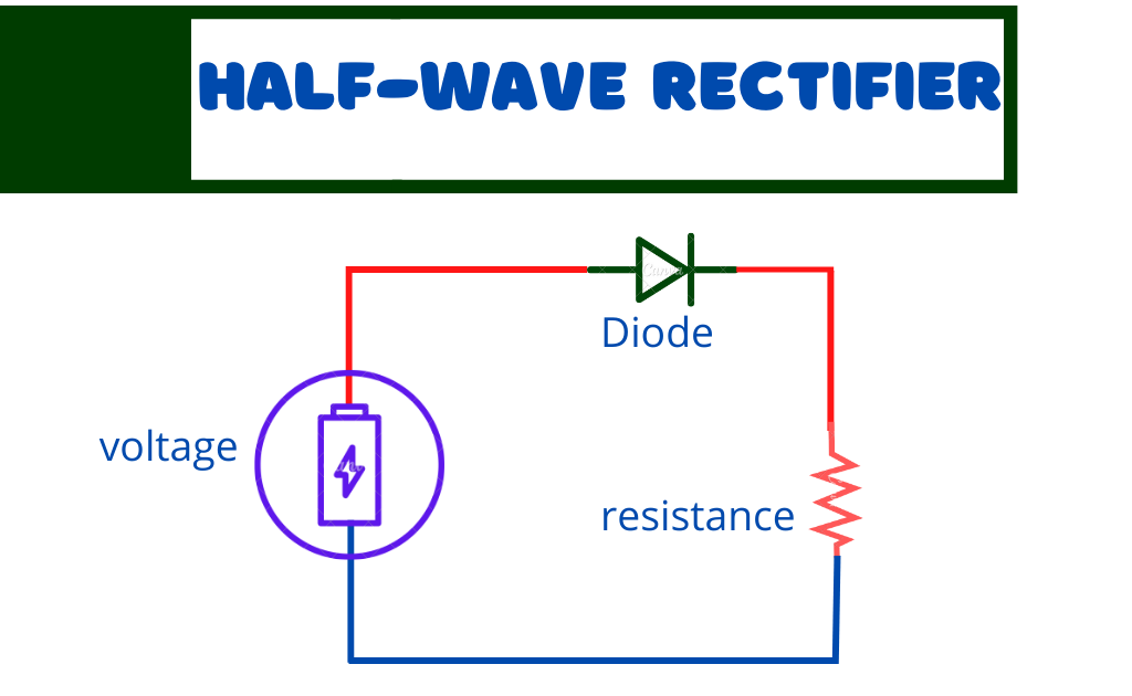
Working of half wave rectifier
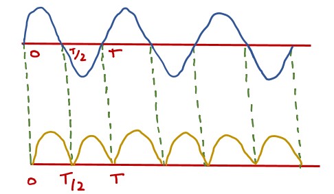
During the positive half cycle of the input 0 to T/2 the diode D is forward biased and offers very low resistance to current and it flows through the resistor R.
This current causes a potential drop across the resistor R in accordance with the alternating input.
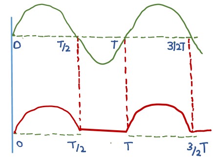
During the negative half cycle T/2 to T the diode is reverse biased and it offers very high resistance and no current flows through R and the potential difference across it is almost zero.
This process is repeated for every cycle. The output voltage is not smooth but appears in pulses and is called pulsating D.C
Full Wave Rectification
That rectifier in which both the input cycles appear as the output DC is called full wave rectification.
It contains four diodes D1,D2,D3, and D4 connected to form a bridge.
The A.C. supply to be rectified is applied diagonally to the opposite ends of the bridge through the transformer or directly. Between the other two ends of the bridge, the load resistor RL is connected.
Working of Full Wave Rectifier
During the positive half cycle of the input voltage, the end P becomes positive and Q becomes negative.
This makes diodes D1 and D3 forward biased while diodes D2 and D4 are reverse biased.
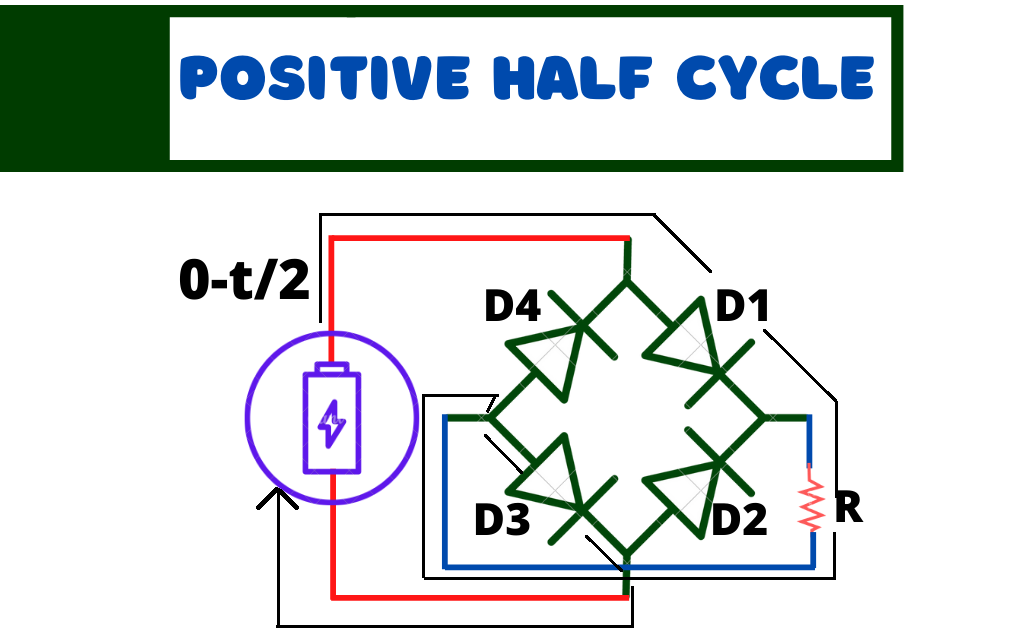
Therefore only diodes D1 and D3 conduct. It can be seen that the current flows from A to B through. During the negative half cycle, the end P becomes negative and the end Q becomes Positive. This makes the diodes D2 and D4 forward biased and D1 and D3 reverse biased.
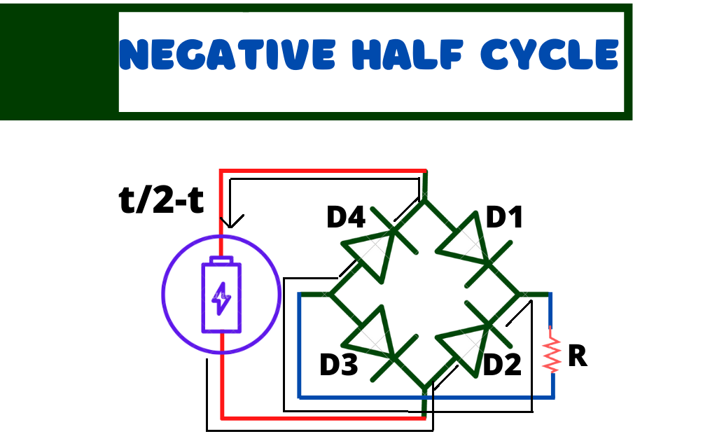
Therefore only D2 and D4 conduct. Now again the current flows from A to B through the load resistor in the same direction.
Therefore D.C output is obtained across the load. The output Voltage is not smooth but pulsating. It becomes smooth by using a circuit called (Combination of capacitors and inductors in the circuit as a filter).
Frequently Asked Question-FAQs
What is the purpose of rectification?
The main purpose of rectification is to provide a steady voltage output for electrical devices and appliances by converting the AC current into DC current.
How many types of rectification?
There are two types of rectification
Half Wave rectification
Full Wave rectification
What is a diode?
The diode is a semiconductor device that allows the flow of current in one direction only. It is used as a rectifier.
What is rectification used for?
All electrical appliances use a DC power supply and a rectifier is used to power them. The conversion of AC to DC power supply can be done using a rectifier in the power supply. Large appliances can be converted from high AC voltage to low DC voltage with bridge rectifiers.

Leave a Reply